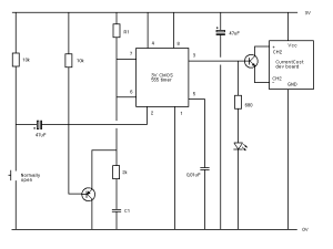
My second CurrentCost development board circuit


My first attempt at monitoring gas use with a CurrentCost development board was partially successful. I could get a reasonable idea of when the boiler was firing but I didn’t really find that information particularly useful. So, plan B was to actually count the pulses from the gas meter. The second circuit, which is described in the 8. More about triggering section of this 555 timer page, has been running ok for a few weeks now, so I’m thinking about actually soldering it together. Thanks to Richard for suggesting VeeCAD, which led me to TinyCad, this is circuit number two (much easier than using MS Paint!).

I’ve been using R1 and C1 values of 122k Ohms and 47u F for the 555 timer, to trigger an output pulse that’s just long enough to get transmitted by the CurrentCost development board (~6 seconds). I may yet tinker with the timing to make it long enough for three transmissions; the time between pulses on the gas meter is long enough and it might make receiving pulses more reliably.

Thanks to Mark and Andrew for some ideas for laying out a circuit on strip board, here’s what I hope is the same circuit using VeeCAD:

Might get the soldering iron out next time Jo’s away!

Update: For plenty more advice on moving from breadboard to a more permanent prototype, have a look on the Evil Mad Scientist Laboratories blog. (11 March 2010)

Update: Finally got round to pulling everything off the breadboard and soldering it together…

…and it actually still works! (14 March 2010)

My first CurrentCost development board circuit


The result of a fair bit of googling and a weekend of hacking is… [drum roll]… a circuit to connect my gas meter to a CurrentCost Envi using a nice little dev board from CurrentCost

cc-circuit

Now I’m much more familiar with messing about with software, not all this messy hardware stuff, so I’m really hoping to get some feedback to improve this early prototype!

So, my theory is that the stuff on the left will trigger the timer on the positive edge of the pulse from the gas meter. R1 and C1 control the 555 timing; more on that in a second. And the stuff on the right (LED and the CurrentCost dev board) should be triggered whenever the gas meter is running and emitting pulses. It all seems to work, except that I can’t seem to get the timing quite right. The gas meter takes about 1m40s between pulses, and I can choose values for R1 and C1 that trigger the output for the right length of time when a single pulse is detected, unfortunately subsequent pulses don’t keep the output on as I was hoping. The best I’ve managed is with R1 = 3M ohms and C1 = 100uF, which does stay on as long as there are pulses from the meter… unfortunately just for a little too long at 5 minutes. Still, at least the CurrentCost Envi will get a reading all the time the boiler is running, and it won’t get stuck on if the meter stops on the portion of the dial where the reed switch is closed.

Any comments with glaring errors, small problems, improvements, or a completely different way to do it?!

Updated: looks like I was having problems with left and right in my first description! Hopefully I’ve got them the right way round now! (2 July 2009)

Update: for an alternative approach (latching a pulse and clearing it when the cc board transmits) take a look at the circuit and photos on John’s blog. (9 July 2009)

Update: an on/off indicator for the boiler hasn’t been all that useful. Instead, to count pulses, I’ve now modified the circuit to simply trigger an output pulse that’s long enough to get transmitted by the CurrentCost development board (~6 seconds). The circuit is described in the 8. More about triggering section of this 555 timer page, with R1 and C values of 122k Ohms and 47u F. (25 January 2010)

Update: posted some more info. on my second CurrentCost development board circuit. (23 February 2010)

GasCost


I’m getting pretty close to getting the gas meter hoked up to CurrentCost. Not quite the finished thing, but was pretty excited when I got this working…

gascost

It’s a 555 timer circuit (using a low power 555 chip) which I’m hoping will keep the CurrentCost dev board transmitting a value as long as the gas meter is running. I’ve since added a capacitor to trigger on an edge so it shouldn’t keep transmitting if the meter stops on the ‘pulse’ position, which is probably around 1/8th of the time on my meter.

I wasn’t quite sure everything was working when I finished last night, but it does seem to do what I want when I was showing Jo this morning, so hopefully all I need to do is get the timing right for the gas meter, rather than me hitting a button every few seconds. More details to follow if it does work.

Home Camp


Home Camp is next weekend so I though it was about time I put something marginally less pointless on my House page; there’s now a quick summary of what I’ve played with so far, instead of the old experimental graphs that were starting to gather dust. Looking forward to getting a few more ideas to add to the list on Saturday.

Update: Unfortunately I wasn’t able to stay the whole day, although I’m very please I made it to the start and still got back in time for Howards wedding. Thanks to the internet, I’ve been catching up on what I missed. In no particular order, here’s a selection of links I’ve found interesting so far:

There’s plenty more to keep up with on the friendfeed HomeCamp room.